

2.6.3.1 Sheet quality
The hard foam air ducts are made of sheets with a minimum density of 30 kg/m3. These sheets are coated on one or both sides with an aluminium foil with a minimum thickness of 60 microns.
Ducts a factory applied aluminium layer suitable for outdoor use;
Sandwich panels made of rigid polyurethane foam and covered with a 500 micron thick aluminium sheet (with relief structure) on the outside and an 80 micron thick aluminium foil on the inside.
The insulation material is foamed up with an expanding agent, for which water is used. Therefore it does not contain CFC, HCFC and HFC.
Aluminium quality exterior layer: EN-AW 3105 in accordance with EN 573/3 The exterior layer is coated with a UV-resistant coating of the type Super Windy, 17 μm thick. UV resistant according to NEN-EN 1396:2015 as RUV:3
The quality of the adhesion between the sheeting and the foam has a value of 1.2kg/cm2 according to NEN-EN 1607.
The density of the PUR is 48kg/m3 with a tolerance of +/- 2kg/m3 in accordance with NEN-EN 1602 and has a light blue colour.
2.6.3.2 Sheet thickness
The hard foam air ducts are manufactured in the minimum panel thickness of 25* mm with a tolerance of +1.5 mm. At this thickness the air ducts are manufactured in such a way, that sufficient stiffness against deformation is present.
Ducts with a factory applied aluminium layer suitable for outdoor use;
The standard thickness of the duct wall/sheet is 30.5mm with a tolerance of +/- 0.5mm.
The sheet is also available with a thickness of 50.5mm with a tolerance of +/- 0.5mm.
2.6.3.3 Cross-connections
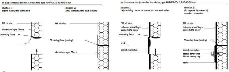
Cross-connections of hard foam air ducts are made in such a way that a sufficiently airtight connection is achieved. We make a distinction here between connections for air ducts in an indoor installation and air ducts in an outdoor installation.
Cross-connections for hard foam ducts for outdoor installation with aluminium outer layer;
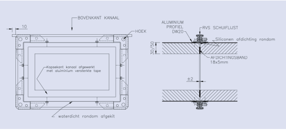
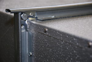
For extra watertightness, a stainless steel sliding strip is hammered onto the top of the DW profile. This should overlap the corner piece by at least 1.5 cm.
2.6.3.4 Longitudinal connections
The ducts are manufactured from a flat sheet, into which v-grooves are cut. These V-grooves are glued. The closing edges are cut at 45°, glued and finished with an aluminium tape with a minimum width of 75 mm and, if necessary, provided with e.g. connection clamps.
If the hard foam air ducts are fitted with a polyester lining on the outside, aluminium tape with a minimum width of 60 mm may be used.
Longitudinal connections for hard foam ducts for outdoor installation with aluminium outer layer;
The ducts are manufactured from a flat sheet, in which V grooves are milled. These V grooves are glued. At the top of the duct, the closing side of the duct is provided with a so-called rain edge. In the rain edge there are stainless steel sheet screws which fix the rain edge on the vertical side of the duct. This prevents rainwater from entering the duct.
It is not allowed to have a partial connection in a duct plane.
2.6.3.5 Stiffening
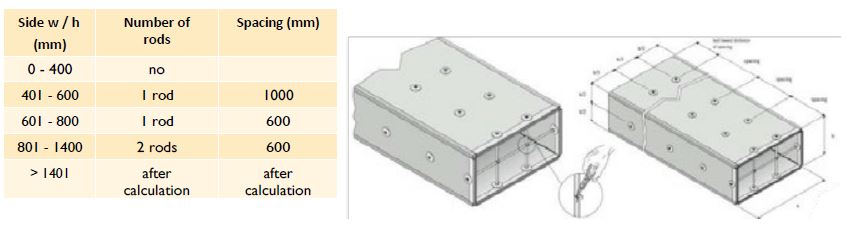
Air ducts are designed to be sufficiently stiff that no troublesome deformations occur. Assuming the application of the minimum sheet thickness in accordance with 2.6.1.2., duct surfaces are stiffened internally > 700 mm.
Depending on the desired specifications or application, the required sheets and stiffening pipes can be made of aluminium or galvanised steel.
Stiffening of exterior hard foam ducts with exterior aluminium layer;
Based on applications of the minimum thickness, duct surfaces are stiffened internally > 401 mm. The holes in the cladding for reinforcing rods are sealed at the factory with silicone sealant. The number of stiffening rods is given in the table below.
2.6.3.6 Execution possibilities
Some of the execution possibilities of hard foam air ducts are;
- PUR foam with an aluminium layer outside and an aluminium layerinside, only suitable for indoor use;
- PUR foam with a glass fibre reinforced polyester outer layer and a aluminium layer inside, suitable for outdoor use;
- PIR foam with an aluminium layer outside and an aluminium layerinside, only suitable for indoor use;
- PIR foam with a glass fibre reinforced polyester outer layer and a aluminium layer inside, suitable for outdoor use;
- PUR foam with an aluminium layer on the inside and a 500 um aluminiumlayer (factory made) on the outside.
For the application of the polyester layer , assuming the application of the minimum sheet thickness according to 2.6.1.2 the following specifications apply:
- 450 gram/m2 glass fleece for an internal duct size < 700 mm;
- 2x 450 gram/m2 glass fleece for an internal duct size ≥ 700 mm.
2.6.3.7 Dimensions
The nominal sizes of the air ducts are given in mm and refer to the internal (net) dimensions with a tolerance of ±2 mm up to a side of 1200 mm and ±4 mm with a side larger than 1200 mm. The dimensions are standardised in accordance with the dimensions of rectangular metal ducts.
2.6.3.8 Visible work
If in an air technical installation a part of the air duct system has to be executed as 'visible work', this will be executed like the other duct work, unless it is mentioned otherwise in the specifications or the construction specifications. Additional measures within the framework of visible work are normally not part of the standard execution.
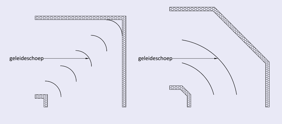
2.6.3.9 Bends
Bends are performed as follows:
- segment bends with an angle greater than 45° should be provided with blades;
- right-angled bends are provided with blades or air turns;
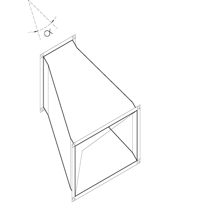
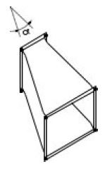
2.6.3.10 Adapters
Adapter pieces are designed so that the top angle α is no more than 60°.
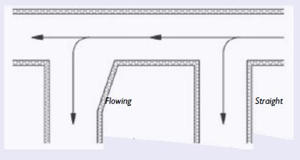
2.6.3.11 Branches
A branch (a split from a continuous main duct) can be realised by means of a straight or a flowing fitting and takes place at an angle of 90° maximum. Aerodynamic aspects also determine the type of execution.
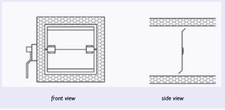
2.6.3.12 Adjustment valves
Adjustment valves are manually adjustable and serve to regulate an installation. They are equipped with a sound locking device which also indicates the valve position. The valve blade is made of a single sheet with a thickness of at least 0.8 mm (executed according to the drawing below) up to a maximum blade width (B) of 300 mm and up to a maximum surface of 0.09 m 2. The edges of the valve blades are rounded and stiffened parallel to the axial direction.
2.6.3.13 Erosion resistance
In order to guarantee erosion resistance, the ducts are finished on the inside with an aluminium coating. The air velocity in the duct system may never exceed 12 m/s.
2.6.3.14 Permissible system pressure
The maximum permissible system pressure is 750 Pa.
During the pressurisation test, the duct in question is pressed once at a test pressure of 500 Pa and once at a test pressure of 1000 Pa.
2.6.3.15 Operating temperature
The maximum operating temperature for hard foam air ducts is 90°C.
The maximum operating temperature of ducts for outdoor installation, provided with an aluminium layer on the outside, is -30 to +65C
2.6.3.16 Transition from plastic to steel
The transition of rectangular hard foam plastic ducts to steel air ducts can be achieved by means of three principles. Which principle is applied depends on the desired transition. The choice of material for the transition depends on the steel air duct to which the duct should be connected, e.g. galvanized steel, stainless steel or aluminium.
- Principle 1: The end side is finished with a metal U-profile;
- Principle 2: the end side is provided with a metal air duct profile;
- Principle 3: A circular mouth is placed at the end or in the duct wall;
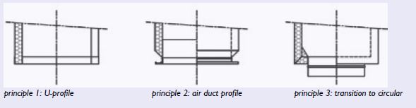
(Note: all seams in the transition must be sealed watertight in external ducts.)
2.6.3.17 Connecting hard foam air ducts to roof ducts
Hard foam air ducts can be connected to roof transits by means of two principles. Which principle is used depends on the desired situation.
Principle 1: The metal air duct extends approximately 50 mm through the roof curb. The transition from metal to plastic is made here. The roof transit is then finished off in a weather-proof manner.
Principle 2: The metal duct is installed under the roof structure. The hard foam air duct is inserted through the roof curb. The roof transit is then weatherproofed. If required, the hard foam/metal transition can be implemented in accordance with the principles outlined in section 2.6.3.16.
For ducts with an aluminium outer layer, a roof transit with air duct profile can also be chosen, on which the hard foam air duct directly connects. Of course, the duct (curb) must be finished weather-resistant.