

2.1.1.1 Sheet quality
For the manufacture of galvanised air ducts, sheet steel is used with anticorrosion zinc-based coatings, applied using the Sendzimir process, in the qualities:
- DX51D Z 275 MAC with a two-sided zinc coating of 275 g/m² according to triangulation test (average thickness of 20 microns per side). Sheet quality/zinc quality according to NEN-EN 10346, tolerances according to NEN-EN 10143.
- DX51D ZMA140 AC with 140 g/m² double-sided zinc coating according to triangulation test (average thickness of 10 microns per side). Sheet quality/zinc quality in accordance with NEN-EN 10346, tolerances in accordance with EN 10143.
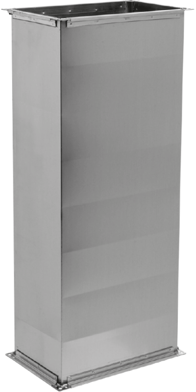
2.1.1.2 Sheet thickness
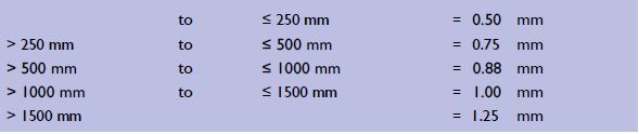
Galvanised air ducts are manufactured with a sheet thickness which depends on the largest duct side, as specified below. The air ducts are
manufactured in such a way that they are sufficiently rigid to withstand deformations and troublesome vibrations. Starting from the largest duct side, the minimum sheet thickness is:
2.1.1.3 Cross-connections
Different types of cross-connections can be applied to rectangular air ducts.
These are company specific, whereby the quality of the sheet, from which the connection profiles are formed, at least comply with that of the material from which the duct is manufactured. Possible applied sliding
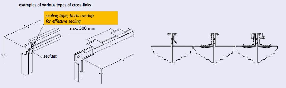
frames must have a minimum double-sided zinc layer of 140 g/m². These crossconnections can (depending on the company) be rolled on or fixed to the duct by means of push-throughs, spot-welds, parkers or pop rivets. The crossconnections are fixed with clips, sliding strips or clamps with a maximum centre-to-centre distance of 500 mm sealing tape, parts overlap for effective sealing (see illustration). A closed cell sealing tape should be fitted between the cross-connections to ensure airtightness, the minimum dimension being W x H = 18 x 4 mm. All four corners are fitted with galvanised bolts and nuts, at least M 6 x 20. If sliding strips are used for the full circumference of the duct, the bolts and nuts at the corners may be omitted. Where necessary, plastic sealant will be applied internally or externally to ensure airtightness.
2.1.1.4 Longitudinal connections
Longitudinal connections between duct sections are generally made using a flange connection. Where necessary, plastic sealant is applied internally or externally to ensure airtightness.
2.1.1.5 Stiffening
The stiffening of air ducts must be such that no troublesome vibrations or deformations occur. This applies to rectangular metal ducts if the largest cross-sectional dimension is ≤ 400 mm, assuming that the minimum recommended thickness of the sheets according to 2.1.1.2 is applied.
If these dimensions are exceeded, additional provisions are required. The degree to which these dimensions are exceeded determines the type of construction of the facilities. For ducts with a side length of > 400 and ≤ 800 mm, the execution forms for the respective duct wall surfaces are:
- cross-breakings; normal outward facing cross-breakings;
- grooves or rings; they are generally arranged transversely to thelongitudinal axis of the duct, at intervals of not more than 500 mm.
For ducts with a side > 800 mm the previously mentioned forms of implementation apply for the duct wall surfaces concerned, whereby surfaces with a surface area of more than 1.5 m² are additionally stiffened by subdividing them into sub-surfaces of no more than 1 m². This additional stiffening in the form of strips, profiles, pipes or sheets are applied internally or externally.
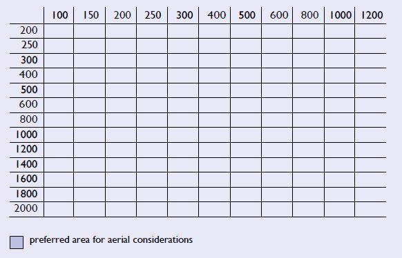
2.1.1.6 Dimensions
The nominal sizes of the air ducts are given in mm and refer to the internal dimensions with a tolerance of +0 to -4 mm. The dimensions are standardised according to NEN-EN 1505 and can be selected as indicated in the table for standard dimensions.
2.1.1.7 Visible work
If in an air technical installation a part of the duct system has to be executed as "visible work", this will be executed like the other duct work, unless it has been mentioned otherwise in the specifications. For duct work designated as visible work, externally applied stickers and indications shall be removed, while the required airtightness will be achieved internally. Additional measures within the scope of visible work are not normally included in the standard design.
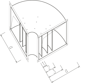
2.1.1.8 Bends
Symmetrical bends
As regards form, symmetrical bends are in principle designed as round bends, i.e. with an inner and an outer radius; the inner radius is 100 mm orgreater (for floor or wall recesses and places where there is no room for an inner radius, an angled inner bend is used). For production reasons, angled inner bends can also be used. In order to limit the resistance in a bend, bends are fitted with blades. No blades are used for:
- bends of 45° or less;
- ducts with a width of 400 mm or less.
The position of the blades shall be determined according to the table below.
Elongated bends
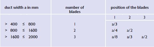
In the case of elongated bends, the smallest duct width determines the number of blades, in accordance with the table above. The ratio for the position of the blades of the largest duct width is then equal to the ratio for the blades of the smallest duct width.
Blade design
The blades are made of single sheet metal. The sheet material is the same as the material from which the duct is made. The design and fixing are of sufficient strength, while the ends of the blades are stiffened.
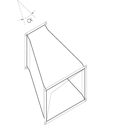
2.1.1.9 Adapters
The adapters are designed in such a way that the top angle α may not exceed 60°.
2.1.1.10 Branches
A branch (split off from a continuous main duct) can be created by means of a rectangular or round fitting. Aerodynamic aspects also determine the types, as shown in the following illustrations.
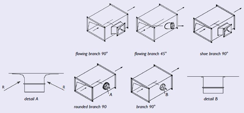
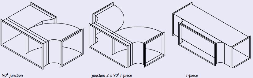
2.1.1.11 Splits
A split is a division of a main duct into two ongoing ducts.
Some examples of splits are:
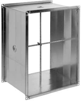
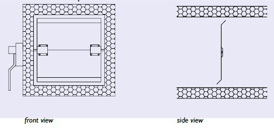
2.1.1.12 Adjustment valves
Adjustment valves are manually adjustable and serve to regulate an installation. They are provided with an appropriate locking device which also indicates the valve position. The damper blade, of the same material as the air duct, is executed in a single sheet with a thickness of at least 0.8 mm (executed according to the drawing below) up to a maximum blade width (B) of 300 mm and up to a maximum surface of 0.09 m². The edges of the damper blades are rounded and stiffened parallel to the axial direction.
2.1.1.13 Tolerances
The maximum tolerance for the length of a straight duct is ± 0.005 x L.
The tolerance for rectangular dimensions is + 0 to - 4 mm.
The maximum tolerance for angles is ± 2°.