

2.2.2.1 Sheet quality
In general, aluminium rectangular ducts are made of sheet material in the quality Al 99.5 / EN AW 1050A. For specific applications, seawater-resistant aluminium of grade AlMg 3 / ENAW 5754 can be used.
2.2.2.2 Sheet thickness
Pipes
The aluminium air ducts are manufactured with a sheet thickness, that depends on the diameter, as specified below.
Based on the diameter, the minimum sheet thickness for standard construction applies:
Fittings
Fittings are executed with a sheet thickness that depends on the diameter. Based on the diameter, the minimum sheet thickness for standard execution applies:
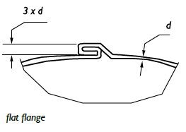
2.2.2.3 Connection in pipes
The connection in the spiral wound belt is carried out in a flat flange, where sufficient stiffness and airtightness is obtained.
2.2.2.4 Connection in fittings
The connection of the seams in fittings is executed in such a way that sufficient stiffness and airtightness is obtained. This connection is made by welding or seaming.
2.2.2.5 Length of pipes
Pipes are supplied as standard in lengths of 3000 or 6000 mm. For technical reasons, the length is in principle not less than the diameter of the pipe with a minimum length of 300 mm.
2.2.2.6 Diameters
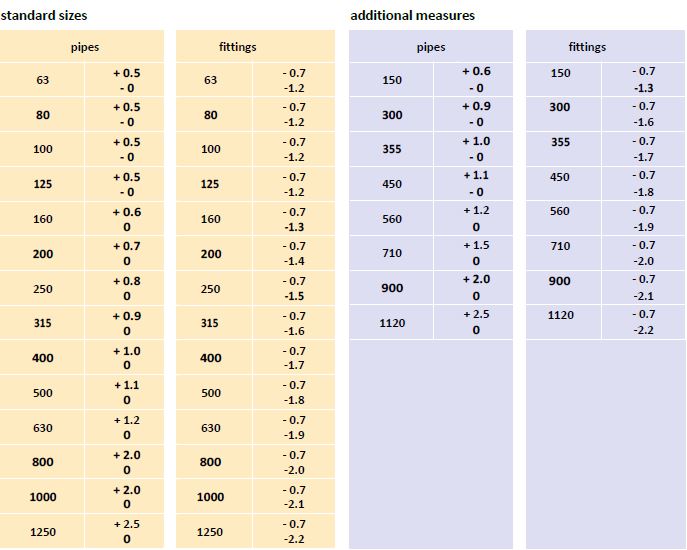
The pipes are produced in the standard diameters that are indicated in NEN-EN 1506, namely 63 - 80 - 100 - 125 - 160 - 200 - 250 - 315 - 400 - 500 -
630 - 800 - 1000 and 1250 mm. Additional sizes, mentioned in the standard are; 150 - 300 - 355 - 450 - 560 - 710 - 900 - 1120 mm.
2.2.2.7 Bends
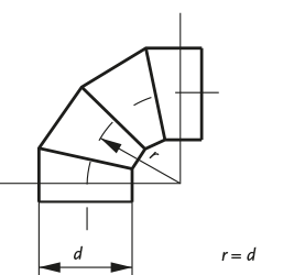
As regards form, bends are manufactured as standard with a radius measured over the centre of the bend and equal to the diameter, except for diameters 63 and 80 where the radius is 100 mm. Standard bends are made in angles of 15°, 30°, 60°, 45° and 90°, in segmented execution with a tolerance of ± 2°. Segment bends 45° consist of a minimum of 3 segments.
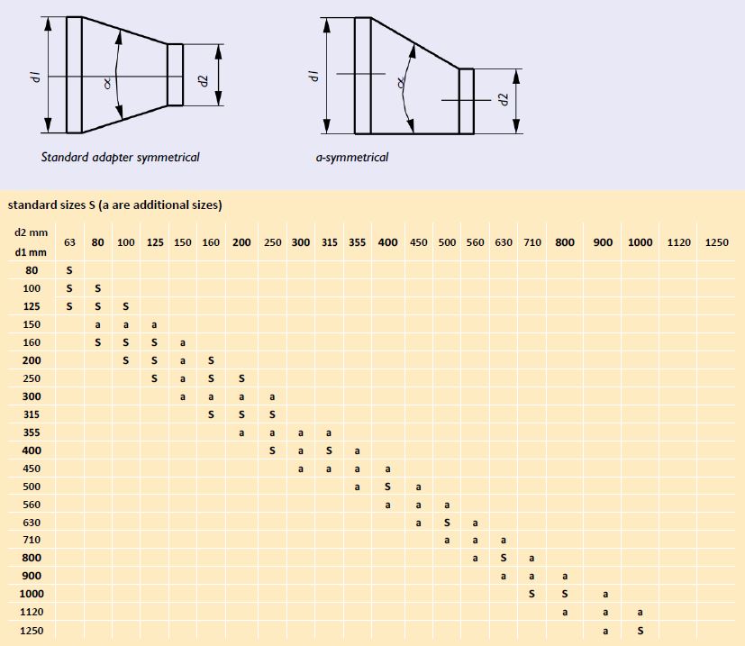
2.2.2.8 Adapters
Adapters can be symmetrical or asymmetrical and have a top angle of minimum 15° and maximum 60°. For pressed adapters the maximum angle is 90°. Symmetrical adapters are used as standard.
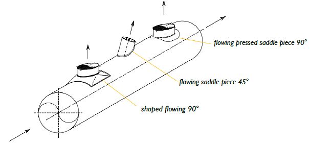
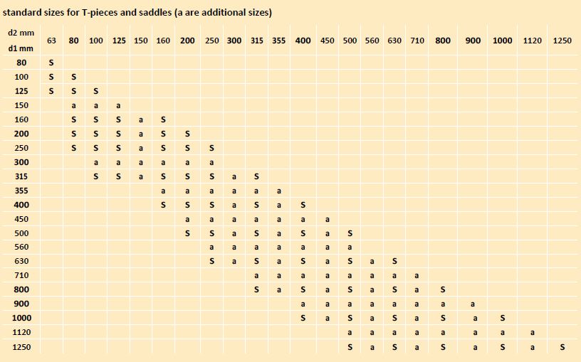
2.2.2.9 Branches
A branch (split off from a continuous main duct) can be established by means of a:
- saddle piece, in combination with straight pipe;
- T-piece, as a complete fitting;
- cross-piece, as a complete fitting; and can be executed as standard inangles of 90° and 45°. Execution in an angle < 45° should be avoided fortechnical reasons.
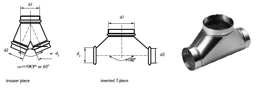
2.2.2.10 Splits
A split is a division of a main duct into two ongoing ducts. It can be accomplished by means of a:
- trouser piece;
- inverted T-piece.
In the case of a trouser piece, the junction can be made at an angle
of α= 90° or 60°. In the case of an inverted T-piece, the junction takes place at an angle α= 180°.
2.2.2.11 Connectors
These find their standard application at:
- connections between pipes;
This fitting, made of the same material as the pipes and fitted with abumper, makes an internal connection. - connections between fittings;
This fitting, made of the same material as the pipes, is smooth and makesan external connection.
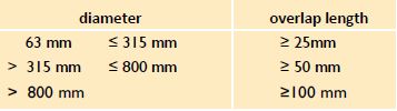
The size of the insertion length of the fittings is attuned to NEN-EN 1506. For the overlap length the following minimum lengths have to be observed:
The connectors are fastened by means of self-drilling parkers and are finished by using:
- Tape with synthetic rubber mass (= self-vulcanizing shrink tape);
- PVC tape only for exhaust ducts;
- Alu-tape only for exhaust ducts;
- linen tape only for exhaust ducts;
- Reinforced PE tape with acrylic adhesive;
- two component tape.
The mentioned tapes should be applied according to the recommendations of the supplier.
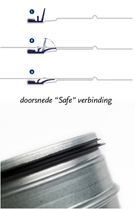
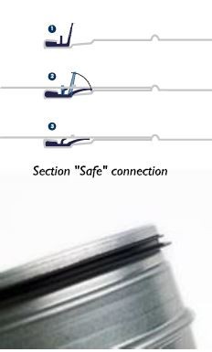
When using round fittings, fitted with a rubber seal (so-called "Safe"), the tape finish is normally omitted for one-time mounting.
The weather / UV resistance of the sealing material to be used must be taken
account for roof ducts.
2.2.2.12 Adjustment valves
Adjustment valves are manually adjustable and serve to adjust an installation. Perforated valve blades should be avoided. See 3.2.4. Adjustment valve – circular for a detailed description.
2.2.2.13 End caps
The caps are made of the same material as the pipes.
2.2.2.14 Tolerances
The maximum tolerance for the length of a duct is ± 0,005 x L.
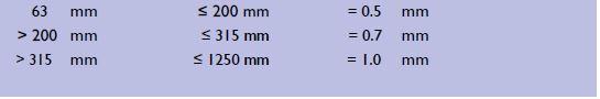
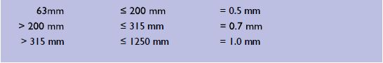
The tolerance for diameters is shown in the table above.
The maximum tolerance for angles is ± 2°.