

2.11.1 General
Luka strives, in close cooperation with suppliers and/or manufacturers of fittings, to limit the occurring air leakage of the air transport route and with that reduce the energy consumption of the air-conditioning installation. The air transport route should be understood to mean
- air ducts;
- between fittings to be mounted;
- Flexible hoses and vent plenums.
2.11.2 Airtightness of air ducts
Only in exceptional cases should a duct system be completely airtight. For safety reasons, a leak is not permissible, for example, in the case of transporting dangerous gases or heavily polluted air. A duct system for a ventilation and air conditioning system manufactured in accordance with standard production methods will show a certain degree of leakage at joints and connections. It is desirable to establish the permissible amount of air leakage for reasons of economy and disturbance. Although the leakage occurs at the cross-connections and longitudinal connections, especially at the corners, it is assumed that the amount of air leakage is proportional with the duct wall surface area. Research has shown that the amount of air leakage per m² of wall area can be written as:
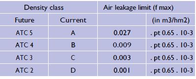
ø LA = f.Ps0.65 (l / s.m²) where:
ø LA = amount of air leakage per m² surface area f = leakage factor
PS = static pressure in Pa
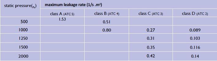
2.11.3 Classes of airtightness
The permissible amount of air leakage is related to airtightness classes, for which a test pressure applies, which is taken from NEN-EN 1507 and 12237. LUKA members test the airtightness only at overpressure. The following classes are used internationally:
If not indicated otherwise in the specifications, Luka uses class C as standard requirement for airtightness. By measuring it can be determined whether the investigated section of the duct complies with the requirement set. In practice, after measuring with an appropriate testing device,the degree of leakage is assessed directly on the basis of a diagram showing the maximum permissible air leakage for mounted duct sections for the given leakage class C.
For the implementation of the leakage test, the following shall be observed:
- the part to be tested is mounted but preferably not provided withexternal insulation;
- the part to be tested is separated airtight from the rest of the system and provided with any intermediate fittings for which the test requirementsare fixed;
- if a total duct system, or the air transport route, is assessed, the area of thesection to be tested shall be between 10 m² and 80 m² (depending on thecapacity of the test apparatus)
- The part to be tested is held at the test pressure (=test pressure) before measuring the leakage volume flow;
- A maximum of 1% of the total surface of the duct project will betested. By default, 1 press test will be performed per project;
- the deviation from test pressure must be about 20 Pa.
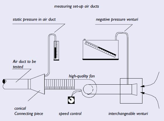
2.11.4 Operating principle
The leak tester basically consists of a fan with adjustable speed, a manometer to measure the pressure in the air duct, a calibrated inlet piece (venturi) and an accurate manometer to measure the suction pressure in the venturi. 3 different inlet pieces are supplied (each with its own curve) to cover the entire range of the leak tester. When the leak tester is connected to the duct section to be tested, the speed is controlled in such a way that the required test pressure is maintained within the set margin. The amount of air lost through leakage is indicated via the venturi of the leak tester. By reading the oblique pipe manometer, the air leakage in l/s can be determined in the table on the leak tester. The measuring instrument shall be calibrated once every 3 years and shall have a measurement accuracy of ± 5 %. In addition to the leak tester described above, it may also be designed in such a way that it can be read digitally. Due to the permanent accuracy, calibration can happen once per 5 years. This is described in EN 1507 and EN 12237.
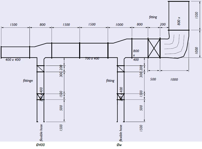
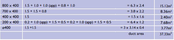
2.11.5 Determination of the surface of the duct to be tested
The following table shows the determination of the number of m² system surface area, which must be used in the formula for the air leakage. In the table a length of 1000 mm is used for the fitting, unless the actual length is greater than 1 metre. In that case the actual length is filled in (see also 6.2 Method of measurement).
Luka leakagetestreport air ducts/air transport
Download the report here.